Air Purge Valves
Vinyl Technology’s waterproof air-purge valves are engineered to deliver controlled air evacuation while maintaining a fully watertight seal, even under repeated compression and extreme environmental conditions. Designed for integration into military and expedition-grade soft goods, these air purge valves enable users to reduce bulk and volume without sacrificing protection.
Built for durability and long service life, Vinyl Technology air purge valves are trusted components in applications where reliability is mission-critical.
Want to learn more? View our air purge valve product brochure for more information on specifications, compatibility, materials, and more.
Controlled Air Release Without Compromising Integrity
These purge valves allow excess air to be expelled after a closure is secured, enabling effective compression of packed contents. Once air is released, the valve prevents re-entry, ensuring the system remains sealed against water intrusion.
Unlike basic venting solutions, Vinyl Technology’s purge valve design maintains waterproof integrity during and after compression without relying on straps or external mechanisms to hold contents down.
Air Purge Valves Engineered for Extreme Conditions
Each air purge valve is designed to perform reliably across a wide range of operational environments, including:
-
Extreme temperatures from –40°F to 130°F
-
0–100% relative humidity
-
Prolonged exposure to water, sand, and field contaminants
-
Repeated compression cycles during active use
The valve construction is engineered to remain functional and watertight throughout the life of the product it is integrated into.
High-Strength, Field-Ready Construction
Vinyl Technology purge valves are built to withstand significant mechanical stress without failure. Key performance characteristics include:
-
High peel strength to resist delamination during use
-
Robust compressive strength to withstand direct pressure
-
Durable internal valve mechanisms that continue functioning after load testing
-
Precision manufacturing to ensure consistent airflow performance
These characteristics make the valves well-suited for demanding military, tactical, and expeditionary applications.
Feel free to call 626-443-5257 or fill out the form above so we can quickly discuss your air purge valve order in detail.
Vinyl Technology’s waterproof air-purge valves are engineered to meet stringent performance requirements for military and expedition-grade applications. Key characteristics include:
-
Waterproof Performance
-
No water leakage through the valve assembly when properly installed
-
Maintains seal integrity during and after compression
-
Tested for waterproofness under sustained water column exposure
-
-
Mechanical Strength
-
High peel strength to resist separation under load
-
Designed to withstand significant compressive forces without structural failure
-
Valve remains fully functional after compressive strength testing
-
-
Airflow Efficiency
-
Engineered air purge mechanism enables rapid evacuation of trapped air
-
Controlled airflow prevents backflow once compression is complete
-
Consistent discharge performance to support repeatable compression cycles
-
-
Environmental Durability
-
Operational temperature range: -40°F to 130°F
-
Functional from 0–100% relative humidity
-
Designed for long-term use in harsh field and storage conditions
-
-
Integration Compatibility
-
Designed for permanent integration into welded or sealed soft goods systems
-
Compatible with waterproof fabrics and assemblies used in military-grade equipment
-
Air Purge Valve Testing
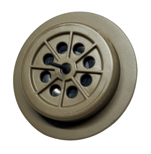
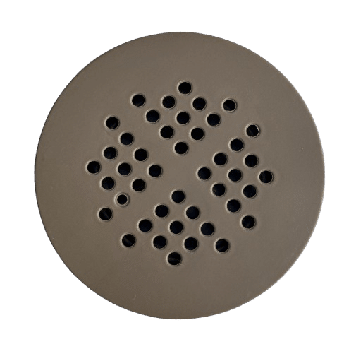
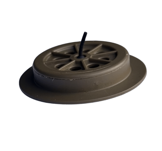
Each type shall include a single one-way air purge valve that complies with Cascade Designs MAD purge valve part number 20-397, Coyote color, or equal. The purge valve shall meet the discharge coefficient, waterproofing, and compressive strength specified in Table II. The air purge valve shall be smooth on the exterior with low profile on the interior that does not exceed 0.35-inch height, and will not snag, abrade or damage stowed contents from the back face of the valve. The valve shall allow air inside the item to be expelled through the valve when the user presses downward during and after closing the item. Exterior air shall not enter through the outside valve surface. The purge shall not degrade from normal field use, storage conditions that are hot/dry, hot/wet, cold/dry or cold/wet chemical contamination (POL, DEET). The valve can be cleaned of dirt by running cool water through the valve from the back side for 10 seconds. The location of the purge valves are specified in Figures 1, 2 and 3 for each type.
| Characteristic | Requirement |
|---|---|
| Finished weight; lbs., max
Type I
Type II
Type III
|
0.90
0.65
0.25
|
| Volume, closed; cubic inch, min:
Type I
Type II
Type III
|
3,400
1,500
350
|
| Seam Shear Strength: lbs, min
Vertical side seam
Curved bottom seam
Horizontal Splice seam
|
220
220
220
|
| Top closure buckle strength; lbs, min
Type I and II: 1-inch
Type III: 3/4-inch
|
300
125
|
| Top Strap peel strength; lbs., min | 12 |
| Purge Valve peel strength; lbs, min | 175 |
| Compressive Strength; lbs, min:
purge valve mechanism
1-inch side-release buckle body
3/4-inch slide release buckle body
|
400
400
400
|
| Bag Waterproofness; min
Seams
Top Closure
Air Purge Mechanism
|
No water leakage
No water leakage
No water leakage
|
| Air purge discharge coefficient: min | 2.0 at a flow rate of 5 cfm. |
| Characteristic | Requirement Reference | Test Method Verification |
|---|---|---|
| Purge Valve Peel Strength | Table II | 1/ |
| Compressive Strength; lbs Purge mechanism |
Table II | Place purge valve at the center of the flat platen of the load cell with exterior surface facing the platen and the back side grill facing up. Use a 1/2-inch steel rod and apply force to the center of the grill intersection at a rate of 0.05-inches per minute to failure or until minimum requirement is exceeded, whichever is reached first. Check for any breakage. The purge valve must properly function after compressive strength is conducted. |
| Buckle Body | Table II | Perform the same test as the purge valve compressive strength, except place the female portion of the side release buckle centered on load cell flat platen and applies force of the 1/2-inch steel rod to the center of the buckle. |
| Bag Waterproofness; Seams; Side and bottom |
Table II | ASTM D751; Raising Column Method, Procedure 2 measured at 50-cm for 30 minutes. The bottom seam specimens shall be sample in the curved area of the seam. |
| Top Closure | Table II | 2/ |
| Air Purge Mechanism | Table II | 3/ |
| Air purge discharge coefficient | Table II | 4/ |
Hold the fabric extension and the grips will be separated at a speed of 2 inches per minute. The peak force measured at breakage shall be recorded to the nearest 0.1 pound.
2/ Waterproof Test for Bag Closure: The waterproof closure test shall be performed on each item type. Condition the top closure area by wetting and air drying the top of the waterproof bag from the top edge, repeat 3 times. Place smooth white cloth or paper towel on a flat and level surface area at least 2 times larger than the footprint of the inverted test specimen which will be centered on it during the test in a well lit area.
Take a dry conditioned bag in the orientation as you would use it (face of bag to the inside/printed label on the outside) and carefully pour one gallon of cold tap water into the bag for Types I and II, and one quart of water for Type III. During the water filling operation, ensure no water contaminates the bag exterior given this will yield an erroneous water leakage failure.
Remove the majority of the air in the bag and close the bag to achieve the proper watertight closure at its maximum volume per the instructions provided on the bag. Invert the bag so that the water is fully and evenly in contact with the bag closure area when standing inverted on a level surface.
Grasp the upper one-third to one-half of the inverted bag and tie a cord hold it gathered. Tie the cord to a horizontal support member hold the bag inverted so that the entire folded edge of the top closure is in contact with the flat level surface. Begin the timer when the bag is inverted and promptly secure the inverted bag so it stands upright.
After the 15 minute test period visually inspect bag the entire bag closure area for any droplets of water over the folded edge. Carefully pick up the inverted bag and examine the paper for wet areas caused by water leaking from the closed inverted bag. Any visual water droplet or wet paper area is considered a leakage failure.
3/ Turn the item inside out so that the exterior of the purge valve is located on the inside of the waterproof bag. Pour one gallon of cold tap water into the compression stuff sack for Types I and II, and one quart of water for Type III. After placing water in the waterproof bag, orient the item so that the water is centered over the purge valve and the fabric is gathered to position the water over the valve, begin the timer.
Suspend the item in this orientation so that water remains centered over the purge valve. Place smooth paper or cloth under the suspended water filled bag so that a visual inspection can determine if water dripped out of valve during the 10 minute test duration.
The purge valve will fail the leakage test if more than 3 droplets of water fall. The droplet can come from one or more locations. Desired performance is no droplets or wetness forming in the 10 minutes.
4/ Air Purge Discharge Coefficient: Mount the Air Purge Mechanism in a fixture which only allows flow through the purge mechanism, allowing for the measurement of flow rate (cubic feet per minute, cfm) and pressure (inches of water column, iwc).
The airflow rate and pressure prior to the purge mechanism shall be measured at a flow rate of five (5) cfm and a discharge coefficient, Cd, shall be calculated from the following equation:
Cd = (Q / dP)1/2
Where:
- Cd is the discharge coefficient
- Q is flow rate, cfm
- dP is differential pressure across the purge mechanism, iwc